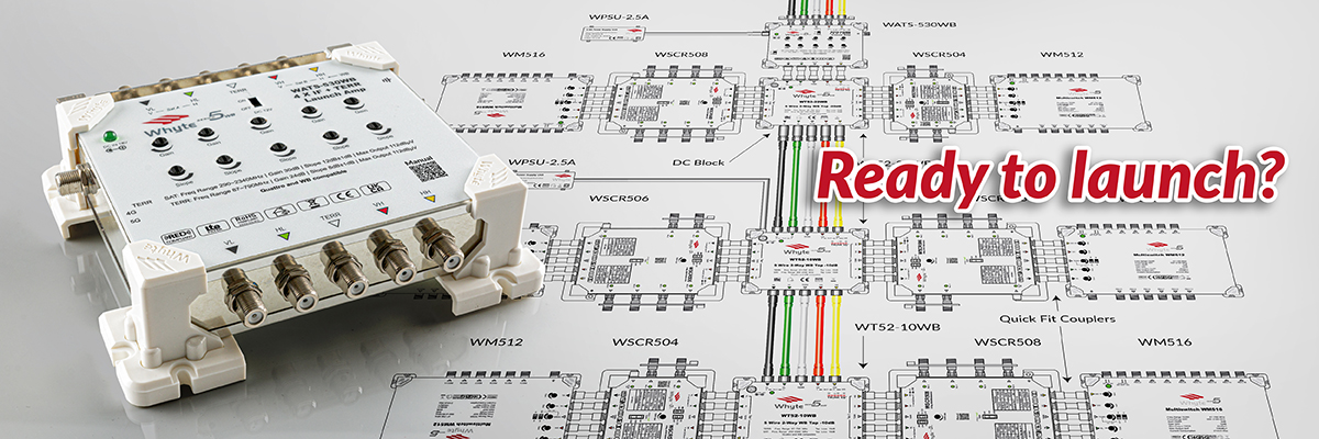
Ready to Launch? When commissioning an IRS installation, careful consideration needs to be given to how we setup our launch amplifiers and their placement in the system. Often a launch amplifier does not need to be the first device in the IRS chain.
So, let’s examine a typical IRS installation from the antenna array to the subscriber outlet starting with the satellite dish. Choosing the appropriately sized satellite dish will of course make a big difference to your system performance. For most medium sized IRS installations an 80cm dish would be ideal, but we should consider that a high gain LNB and a relatively short cable drop to your headend will result in a high-level input signal scenario. A similar scenario can of course occur for terrestrial where we are relatively close to the transmitter with a high gain antenna.
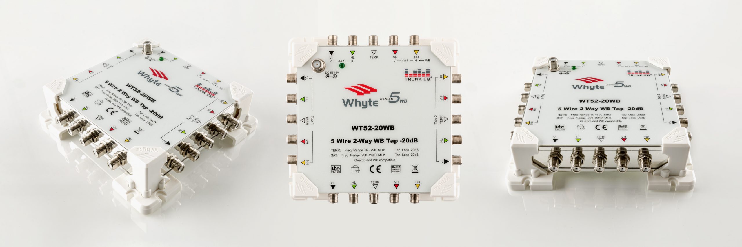
In many instances a Launch Amplifier at the top of a high input level system would not be required. It would be more beneficial to place our Launch Amplifier further down the chain after a series of Whyte Taps. Whyte Taps have a typical loss of 4dB and have Trunk EQ which equalises the spectrum to correct the slope.
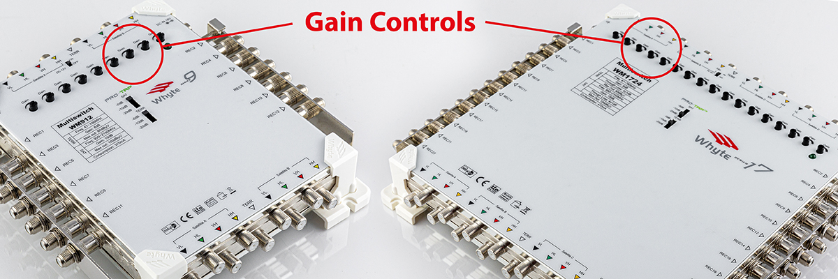
Whyte Launch Amplifiers feature manual Gain Control per SAT and TERR path enabling you to accurately set the required launch levels for distribution. System planning defines the required launch levels and helps us optimise the system performance at the point of commissioning.
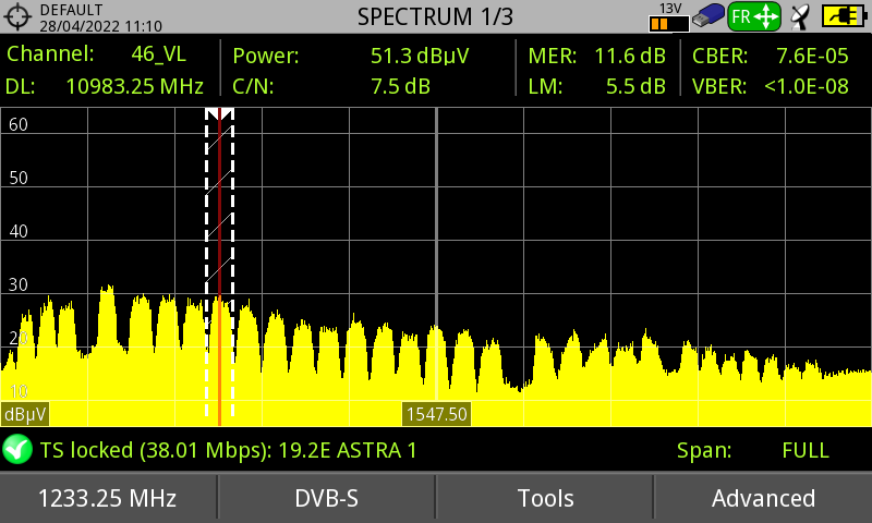
Let’s take a closer look at slope. Here we’re going to assume that we are using CAI approved coaxial cable. The attenuation of signals at 2150MHz is approximately 3dB per 10m of cable length, while at the lower end of the satellite spectrum (950MHz) the attenuation is less at about 2dB per 10m. From this we can estimate that over the distance of 100m of cable, 10dB of slope will be introduced.
To counteract the effects of slope we can pre-emphasise the signals by introducing a positive slope. All Whyte Launch Amplifiers have manual slope control for each SAT and TERR path built in. In an ideal world the spectrum response should be flat at the middle distance to the subscriber outlet. This provides a slightly negative slope on the longest runs and slightly positive on the shortest ones thereby keeping the slop to acceptable levels. To calculate the amount of positive slope required, determine your middle-distance cable length, and divide this number by 10. This will give you an approximation of the amount of positive slope required at the Launch Amplifier.
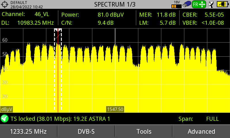
Negative slope (200m coax)
Flat response
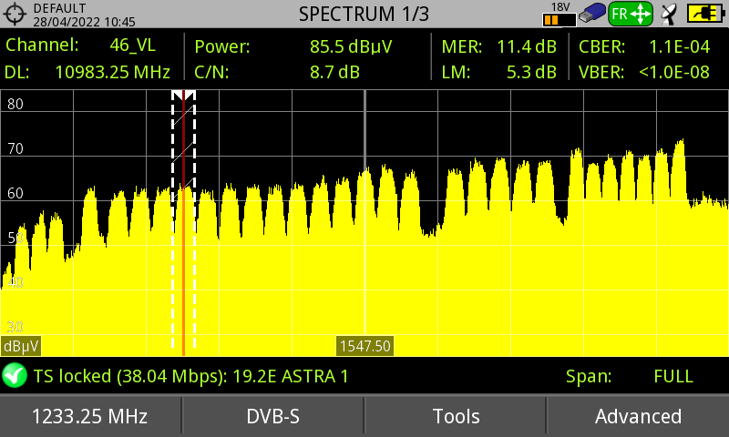
Positive slope
Every installation is unique and we’re here to help you get the most out of your Whyte IRS equipment. We offer a free of charge system planning and sound advice that’s only a call or email away.